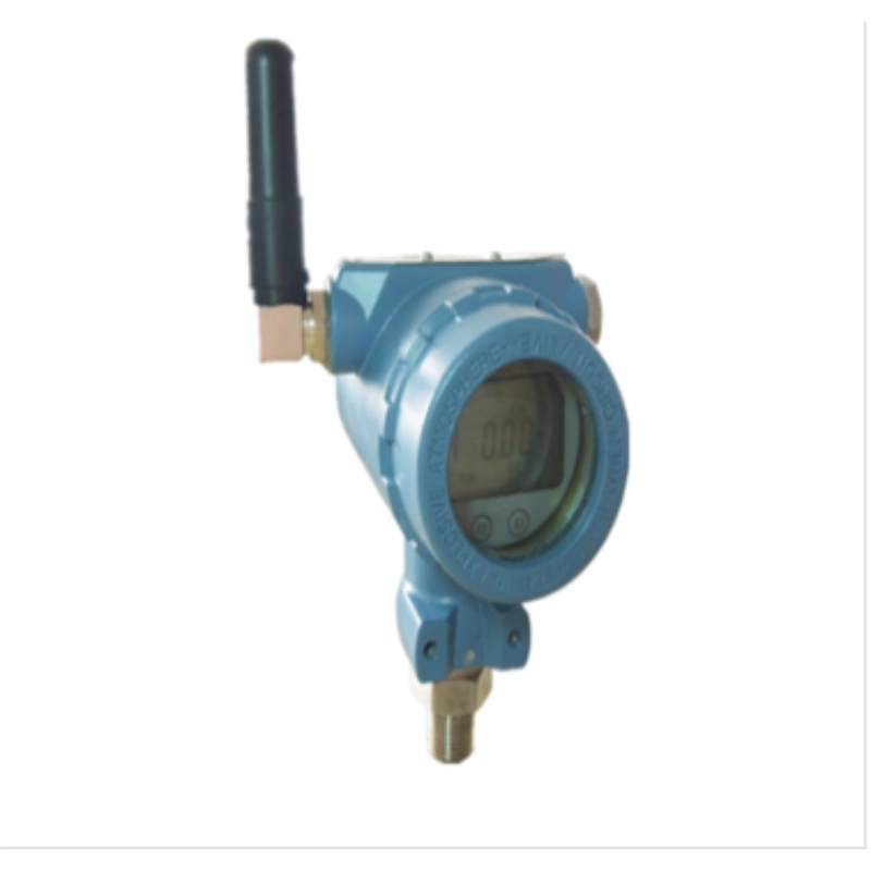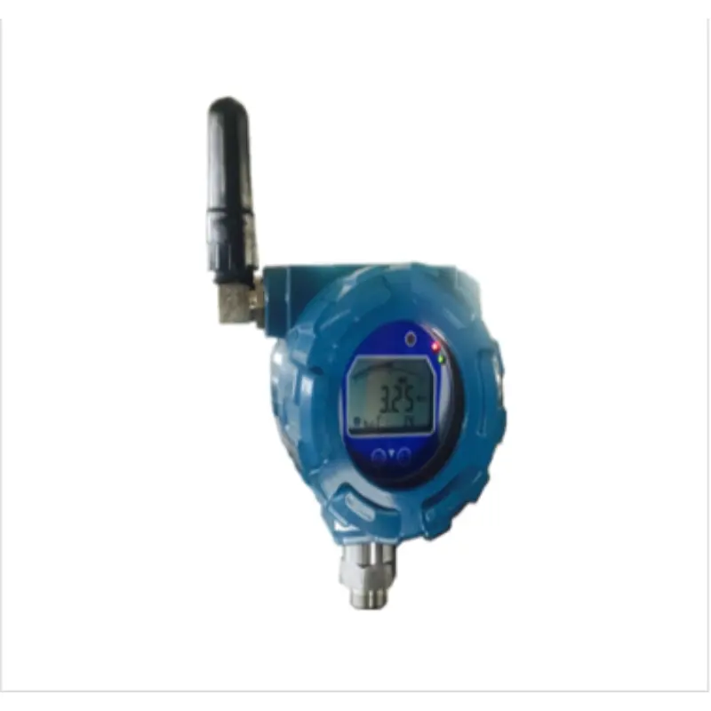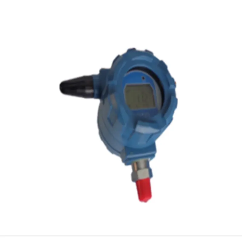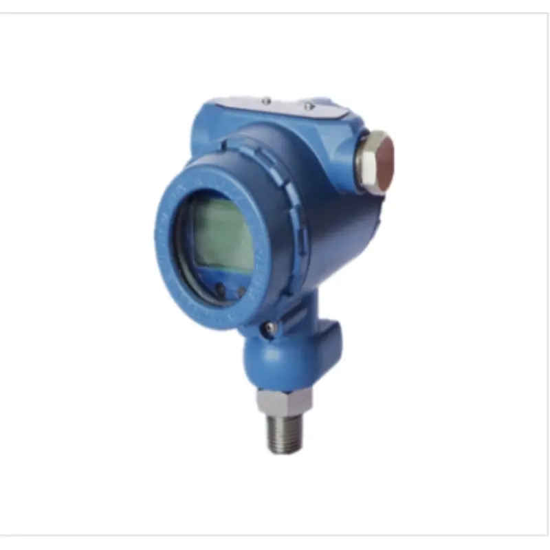
Pressure Transmitter/SM39PCRD Wired Digital Pressure Transmitter
Product Categories Pressure transmitter
Pipeline pressure testing has been widely used in major oil and gas fields and other industrial pressure testing fields across the country; Explosion-proof, fully sealed and waterproof design; Synchronous signal output 4~20mA, RS485, optional on site; Adjustable installation direction: connected to the on-site pipeline valve through a live joint or adapter, the direction can be adjusted.
1. Features
- Pipeline pressure testing has been widely used in major oil and gas fields and other industrial pressure testing fields across the country;
- Explosion-proof, fully sealed and waterproof design;
- Signal synchronous output 4~20mA, RS485, field optional;
- Adjustable installation direction: It can be connected to the on-site pipeline valve through a union or adapter, and the direction can be adjusted.
2. Technical indicators
- Working environment: temperature, -40℃≤Tamb≤+65℃; atmospheric pressure: 80KPa~110kPa; humidity: 5%RH~95%RH
- Power supply: 24VDC
- Measuring principle: Piezoresistive
- Output signal: 4~20mA & RS485 optional; 4.5-digit LCD display.
- Case material: cast aluminum, protection level: IP67
- Contact medium material: 316L
- Electrical connection: NPT1/2″(F), M20*1.5
- Process connection: NPT1/2″(M), R1/2″(M), M20*1.5(M), adapter: NPT(F) 1/2″-R1/2″(M)
- Measuring range: 0~ 0.16, 0.4, 0.6, 1.0, 1.6, 2.5, 4, 6, 10, 16, 25, 40, 60MPa, etc. (customizable), accuracy level: 0.5.
- Dimensions: Height 165 x Width 106 x Depth 130; Weight: 1kg
- Explosion-proof certification: Explosion-proof certificate number: CE18.1519 Explosion-proof mark: EXd IIC T6 Gb
3. Dimensions
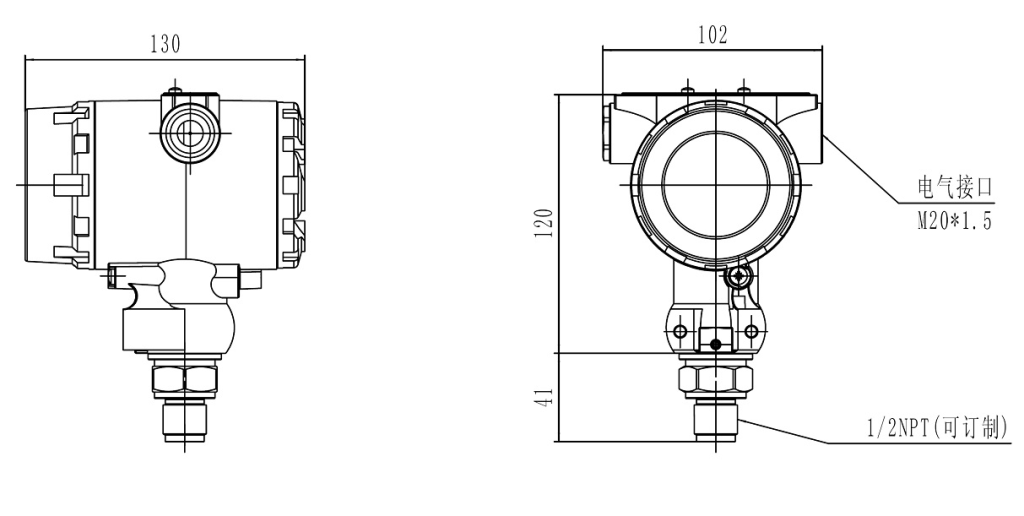
3. Installation and debugging instructions and wiring definition
3.1. All transmitters are digitally calibrated, and different transmitters are completely consistent and interchangeable;
3.2. To install the pressure transmitter on site, you need to unscrew the back cover of the meter head, connect the cable from the electrical interface, and connect the wires correctly according to the wiring definition. After the wiring is completed, please tighten the back cover to ensure waterproofing.
3.3. To install the pressure transmitter on the pipeline, first close the corresponding valve, and then there are two installation methods: (1) screw the transmitter directly into the upper port of the valve; (2) screw the union or adapter into the upper port of the valve, and then screw the transmitter into the upper port of the union or adapter. This method increases the adjustable direction of the union or adapter. After the installation is completed, open the needle valve to confirm that there is no leakage, which means the installation is qualified;
3.4. Definition of green terminals for 8-core wiring. (1) 1.5 pins - 24V power supply +, 2.6 pins - 0V power supply -, 3.7 pins - 485_A, 4.8 pins - 485_B.
For on-site 485 communication, you need to connect pins 1234, 1-2 for power supply, and 3-4 for communication AB.
For on-site 4-20mA communication, just connect pins 1-2.
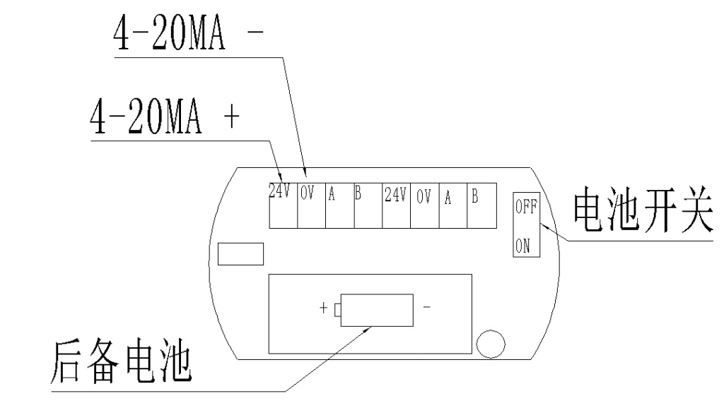
(2) The main signal is a two-wire 4-20mA RS485 interface. It should be noted that when using RS485 and 4-20mA at the same time, the number of digital communication network connections cannot exceed 10. The RS485 interface cannot increase the terminal resistance, otherwise it will cause the 4-20mA current jump and destroy the 4-20mA current signal. If only the RS485 signal is used, there is no limit on the number of parallel connections, and a maximum of 255 units can be connected in parallel.
Notice:
1. The driving capability of the passive RS485 converters currently on the market is limited, so when there are a large number of parallel connections, please choose an active isolated RS485 interface.
2. Due to the reasons of grid connection, the board does not have bus matching resistors and pull-up and pull-down resistors for the RS485 bus. If the RS485 interface used by the customer does not have pull-up and pull-down resistors, it may cause the bus static level to be uncertain and erroneous data to be generated on the RS485 bus. Therefore, the customer or system integrator should add matching resistors and pull-up and pull-down resistors outside the bus to set the bus static state.
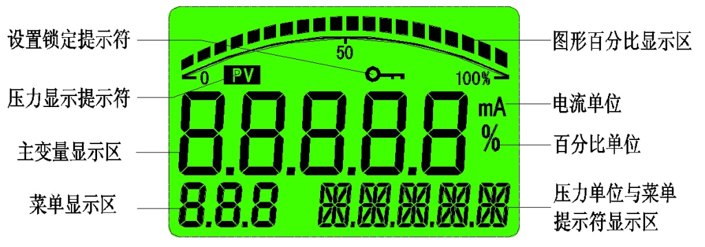
3.5 Display panel indication definition
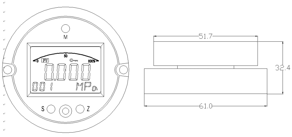
3.6 On-site setting of basic instrument communication information
The instrument protocol is also built-in. It supports MODBUS_RTU protocol. The software adopts green installation-free technology. It will automatically decompress the required dynamic link library when used. Therefore, please set this software to the whitelist in the anti-virus software of the computer to prevent security software from blocking the normal operation of this software.
The software supports serial ports in the range of 1-15. If you use a USB-to-serial port, please change the port number to within 1-15.
In addition, after testing, the USB/RS485 converter is currently used more frequently. There are many types of USB conversion chips used in it. It is currently found that the converter using the FDT232 chip needs to set the driver, otherwise it will cause this software to fail to read the transmitter data. The setting page is as follows:

In the advanced settings of the FDT232 software driver, open it in the device manager and you will see a BM option. This setting should be changed to 1. The default setting of general software is 15, so you must change this setting to use the serial port normally. No such problem has been found in USB converters with other chips.
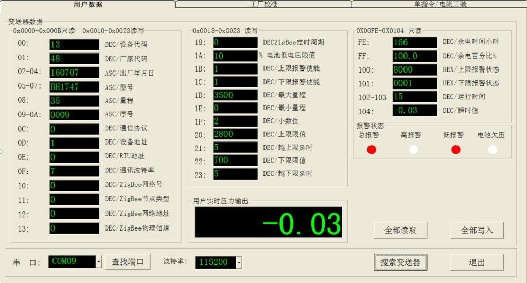
1.Find the port:
When the software is started, it will automatically search for available ports on the machine. Please select the correct port number and the baud rate that matches the transmitter. Click the search button to search for online transmitters. There is a search result prompt at the bottom of the software. List all available port numbers on this computer. If there is a dynamically pluggable USB virtual port, you can click "Find Serial Port" to update the listed information.
2."Search for transmitters:
That is, search for online transmitters, and the search address range is 1-255. If found, it will be prompted in the status bar. If you want to end the search early, please click again. Pay attention to the baud rate band. The search is only for the currently set baud rate range.
3."Read All":
After the search stops, the software will automatically read all the parameters of the first transmitter. And continuously read the alarm status, real-time measurement value, instrument status, ADC value. Clicking the Read All button can also update all current data.
4. "Write All":
After all data modifications are completed, click "Write All" to save it to the transmitter.
Note that the cyan text box on the software supports customers to modify the content, and the red box is the default data of the transmitter.
Additional notes:
The software has expressed it in a separate address representation according to the agreement provided by the customer. The data type after the data frame indicates the type of this data.
DEC represents decimal data. HEX represents hexadecimal data. Character represents text characters, which is ASCII code. For detailed protocols and data meanings, please refer to the protocol text provided by the customer.
3.7. Panel button configuration
This circuit has three buttons and an LCD display window:

7.1Panel buttons:
The function of the M key is mainly the mode key, which switches between data and menus. When the mode key is in non-setting mode of the transmitter, long pressing it will execute the main variable clearing function. Whether to execute it needs to be selected by the S and Z keys.
The function of the S key is mainly to add data. In non-setting mode, long pressing the S key will enter the active transmission high limit setting mode. At this time, it is necessary to pay attention to the significance of pressure.
The main functions of the Z key are data shift and subtraction. In non-setting mode, long pressing the Z key will enter the active zero setting mode.
In the measurement mode, click the M key to enter the password setting mode. You need to set a password to enter the setting mode. If the password is incorrect, the transmitter will exit to the measurement mode.
The board has active range migration scaling and passive range migration scaling. The passive setting requires the user to enter the configuration setting mode.
The following are the agreed button states:
The abbreviation of S key single click is: S The abbreviation of Z key single click is: S The abbreviation of M key single press is: M
M key long press for ML
S long press: SL Z key long press: ZL
7.2The following is the passive configuration panel button setting process:
Panel layout diagram:
Setting menu flow chart:

In the END menu, press the M key to exit the setting mode and save the data. In other menus, long press the M key to exit the setting mode, but the data will not be saved.
There are two OUT menus in the figure, one is the FIX menu and the other is output linearization.
In the setting menu above, the corresponding menu data meanings are:


- Active migration and master variable clearing
Entering the active migration and main variable clearing states requires normal working mode.
Make sure the pressure is valid when setting the active migration. Otherwise, the output of the transmitter will be abnormal.
There is a range limit for clearing the primary variable. Generally, the value needs to be near 0 or near the zero pressure. The limit range is 10%. If it exceeds this range, the clearing operation will not be performed.

3. Switch monitors
a. The main screen display and auxiliary screen display area of the screen have multiple display functions. The main screen display has three types: pressure value display, percentage display, and current display.
b. The auxiliary screen display has two options: temperature display and slave address display. The temperature value comes from the temperature sensor on the circuit board.


Display switching can be performed at any time. The display mode after each power-on depends on the mode value when the software was last saved. The display mode set on the panel button will be cleared after the next power-off.
The battery level display function is located on the upper right corner of the LCD screen. There are 5 progress bars for the battery level. The more bars there are, the more sufficient the battery level is. The battery will automatically cut off the output when the battery voltage is lower than 3.0V.
This transmitter uses a dual power supply system. In addition to the normal power supply, there is also a built-in battery power supply mode. Turn on the battery power supply of the transmitter through the SW switch, and the transmitter works in the battery power supply mode. For example, when the built-in battery capacity is 2000mA/h, the longest working time of the battery power supply of this machine can reach 300 hours, which is about 12.5 days. Regardless of whether it is a built-in battery or not, if the external power supply is turned on, the instrument will automatically use the external power supply first and output a 4-20mA current signal.


