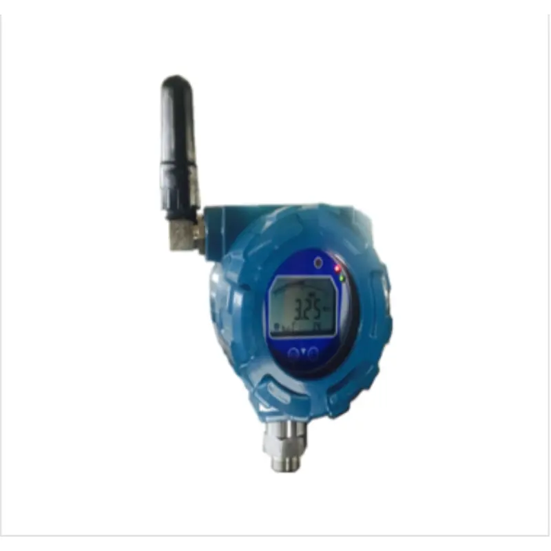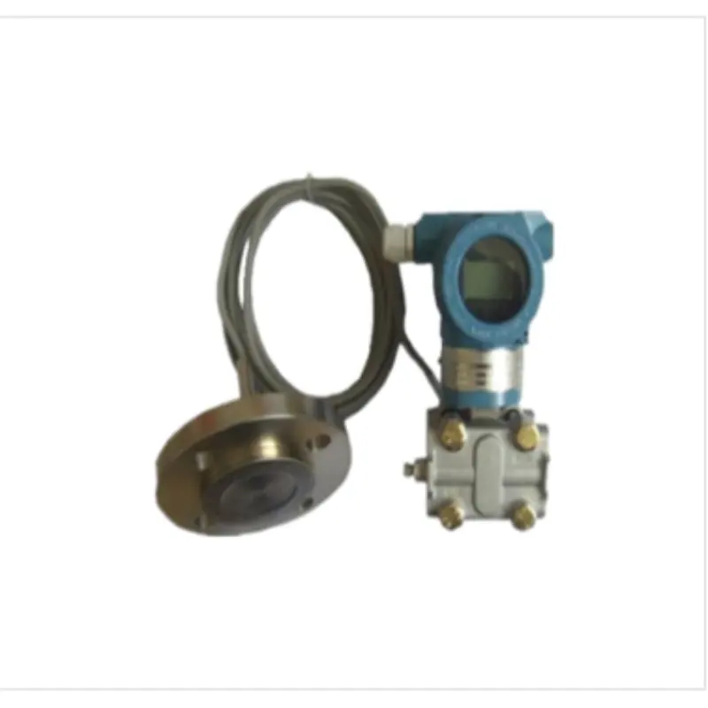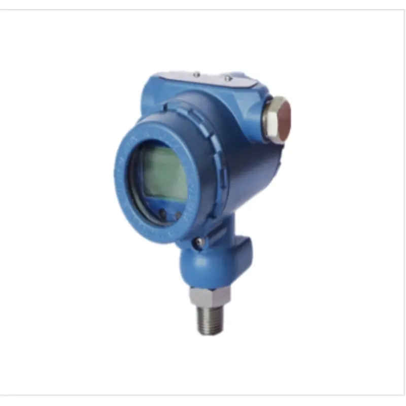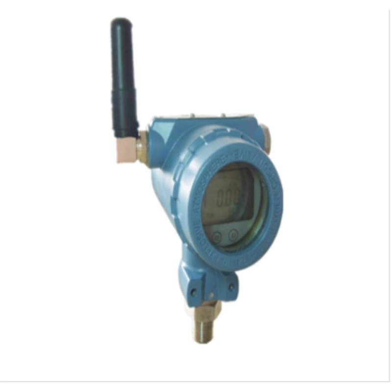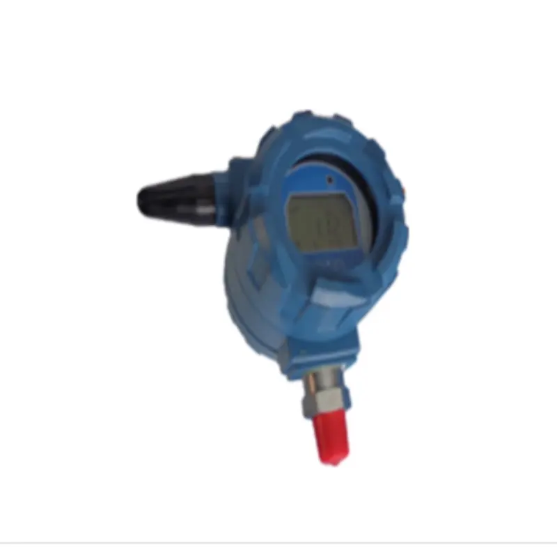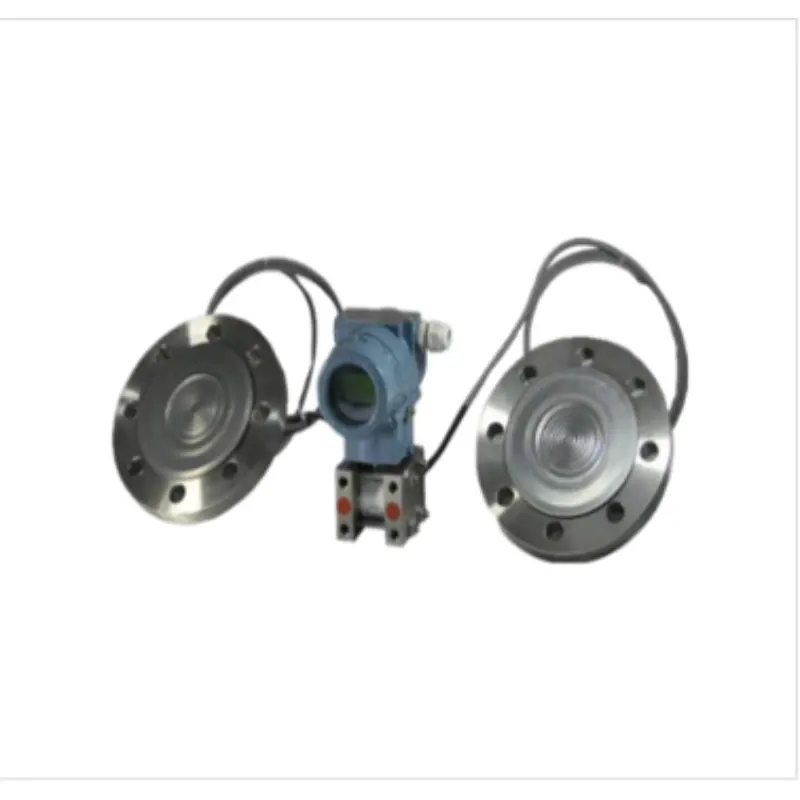
Pressure transmitter/SM39PWB-SFLYC double flange remote diaphragm pressure transmitter
Product Categories Pressure transmitter
The SM39PWB-SFLYC double flange remote transmission diaphragm pressure transmitter is composed of the SM39PWB-CY series differential pressure transmitter and the remote transmission flange with capillary installed by welding. Its working principle is the same as that of the CY series differential pressure transmitter (CY series differential pressure transmitter technical specification), but the pressure transmission path is slightly different: the pressure acting on the remote transmission flange side first passes through the diaphragm and filling liquid on the remote transmission flange, then through the capillary, and finally reaches the corresponding positive and negative sides of the measuring sensor.
- application
The diaphragm box of the double-flange remote diaphragm pressure transmitter is used to prevent the medium in the pipeline from directly entering the pressure sensor component of the transmitter. Silicone oil and other filling liquids are used to transmit pressure between it and the transmitter.
SM39PWB-SFLYC double flange remote diaphragm pressure transmitter is used to measure the level, density and pressure of liquid, gas or steam, and then convert it into 4mA~20mADC HART current signal output. It can also communicate with HART handheld terminals to set parameters and monitor processes.
The measuring range of SM39PWB-SFLYC double flange remote transmission diaphragm pressure transmitter (when not migrated) is 0-1kPa~2MPa, and the rated pressures of the remote transmission flanges are: 1.6/4MPa, 6.4MPa 10MPa, 150psi, 300psi or 600psi.
- How it works
The SM39PWB-SFLYC double flange remote transmission diaphragm pressure transmitter is composed of the SM39PWB-CY series differential pressure transmitter and the remote transmission flange with capillary installed by welding. Its working principle is the same as that of the CY series differential pressure transmitter (CY series differential pressure transmitter technical specification), but the pressure transmission path is slightly different: the pressure acting on the remote transmission flange side first passes through the diaphragm and filling liquid on the remote transmission flange, and then through the capillary to reach the corresponding positive and negative sides of the measuring sensor.
- enter
Measuring parameters: differential pressure, liquid level measurement range
Lower limit: -100%URL (continuously adjustable)
Upper limit: to +100%URL (continuously adjustable)
Range
Table 1 Comparison table of range codes and ranges
| Range code | Minimum range | Maximum range | Rated pressure (maximum) |
| B | 1kPa | 6kPa | Remote flange rated pressure |
| C | 4kPa | 40kPa | |
| D | 25kPa | 250kPa | |
| E | 200kPa | 2MPa |
Table 2 Comparison table of remote transmission flange and minimum measuring range
| Flange level | Nominal diameter | Minimum range | |
| One-way remote transmission | Bilateral remote transmission | ||
| Flat | DN50/2〞 | 10kPa | 10kPa |
| DN80/3〞 | 6kPa | 1kPa | |
| DN4" | 6kPa | 1kPa | |
| Plug-in | DN50/2〞 | 16kPa | 16kPa |
| DN80/3〞 | 6kPa | 1kPa | |
| DN4" | 6kPa | 1kPa | |
The minimum range of the remote transmitter should be the larger value of the minimum range in Table 1 and Table 2. The adjusted range shall not be less than the minimum range. The maximum range of the remote transmitter should be the minimum value of the maximum range of the transmitter body and the rated pressure of the liquid level flange.
Output Output signal
Two-wire system, 4mA~20mADC HART output, digital communication, HART protocol is loaded on 4mA~20mADC signal. Output signal limit: Imin=3.9mA, Imax=20.5mA
- Response time
The damping constant of the amplifier component is 0.1s; the time constant of the sensor and remote flange is 0.2s to 6s, depending on the sensor range, range ratio, capillary length, and filling fluid viscosity. The additional adjustable time constant is: 0.1s to 60s.
- General conditions
-
- Installation conditions
The transmitter body can be directly fixed in any position. The best state is to make the process flange axis in a vertical state, and the position deviation will produce a correctable zero offset. The electronic case can be rotated up to 360°, and the positioning screws can fix it in any position. The remote flange is connected to the matching flange that meets the ANSI/DIN standard. The matching flange should be equipped with a soft gasket and mounting bolts and nuts (the user can choose the mounting bolts and nuts). For double-sided flange remote transmitters, the capillary component and the remote flange should only be installed in the same ambient temperature. The minimum bending radius of the capillary is 75mm, and winding is strictly prohibited!
-
- Environmental conditions
Ambient temperature
Minimum: Depends on filling fluid
Maximum: 85℃
With LCD display, fluororubber sealing ring -20℃~65℃ Storage temperature/transportation temperature
Minimum: Depends on filling fluid Maximum: 85°C
Relative humidity: 0%~100%
Shock resistance Acceleration: 50g
Duration: 11ms
Vibration resistance 2g to 500Hz
Electromagnetic compatibility (EMC)
See Table 4 "Electromagnetic Compatibility Appendix" on the next page
-
- Process medium temperature limit
Medium temperature: -30℃~400℃
Table 3 Relationship between filling fluid, operating temperature and minimum operating static pressure
| Filling fluid | Silicone oil (S) | High temperature silicone oil (H) | Ultra-high temperature silicone oil (U) | Vegetable oil (V) |
| Density (25℃) | 960kg/m³ | 980kg/m³ | 1020kg/m³ | 937kg/m³ |
| Operating temperature range | -30℃~200℃ | -10℃~350℃ | -10℃~400℃ | 0℃~250℃ |
| temperature | Working static pressure range (kPa absolute pressure) | |||
| 20℃ | >10 | >10 | >10 | >25 |
| 100℃ | >25 | >25 | >25 | >50 |
| 150℃ | >50 | >50 | >50 | >75 |
| 200℃ | >75 | >75 | >75 | >100 |
| 250℃ | >100 | >100 | >100 | |
| 350℃ | >100 | >100 | ||
| 400℃ | >100 | |||
Note: If the working temperature and static pressure relationship exceeds the above range, it should be specially pointed out. The requirements can be met through special design.
From 3.5kPa absolute pressure to rated pressure, the protection pressure can be greater than 1.5 times the rated pressure and applied to both sides of the transmitter.
ANSI standard: 150psi~600psi
DIN standard: PN 1.6MPa~PN 10MPa
One-way overload limit
The low-pressure side is the rated pressure of the transmitter body, and the high-pressure side is the rated pressure of the remote transmission flange. Correctable zero drift may occur.
weight
Single-side remote transmission: DN 50/2″ is about 7-10kg, DN 80/3″ is about 8-11kg, DN 4″ is about 9-12kg;
The double-sided remote transmission is about 10-16.5kg for DN 50/2″, about 12-18kg for DN 80/3″, and about 14-21kg for DN 4″.
-
- Power supply and load conditions: Power supply voltage is 24V
R≤(Us-12V)/Imax kΩ Where Imax=23 mA
Maximum power supply voltage: 42VDC
Minimum power supply voltage: 12VDC, 15VDC (backlit LCD display) Digital communication load range: 250Ω~600Ω
Material
Measuring membrane box: stainless steel 316L
Diaphragm: Stainless steel 316L, Hastelloy C, Tantalum Process flange: Stainless steel 304
Filling fluid: Silicone oil, high temperature silicone oil, ultra-high temperature silicone oil, vegetable oil
Sealing ring: Nitrile rubber (NBR), fluororubber (FKM), polytetrafluoroethylene (PTFE) Transmitter housing: Aluminum alloy, with epoxy resin sprayed on the surface
Housing seal: Nitrile rubber (NBR)
Nameplate: Stainless steel 304
Electrical Connections
M20X1.5 cable gland, terminal block is suitable for wires with diameters of 0.5mm2 to 2.5mm2. Process connection
The transmitter has NPT 1/4 internal threads on the low pressure side.
The level flange on the high pressure side of the transmitter complies with ANSI or DIN standards. It can be directly installed, refer to the overall dimensions. Enclosure protection level: IP67
Table 4 Electromagnetic compatibility appendix
| Serial number | Test items | Basic Standards | Test conditions | Performance level | |
| 1 | Radiated interference (housing) | GB/T 9254-2008 Table 5 | 30MHz~1000MHz | qualified | |
| 2 | Conducted interference (DC power port) | GB/T 9254-2008 Table 1 | 0.15MHz~30MHz | qualified | |
| 3 | Electrostatic Discharge (ESD) Immunity | GB/T 17626.2-2006 | 4kV (contact) 8kV (air) | B | |
| 4 | Radio frequency electromagnetic field immunity | GB/T 17626.3-2006 | 10V/m (80MHz~1GHz) | A | |
| 5 | Power frequency magnetic field immunity | GB/T | 17626.8-2006 | 30A/m | A |
| 6 | Electrical fast transient burst immunity | GB/T | 17626.4-2008 | 2kV(5/50ns,5kHz) | B |
| 7 | Surge immunity | GB/T | 17626.5-2008 | 1kV (between lines) 2kV (between lines and ground) (1.2us/50us) | B |
| 8 | Immunity to conducted disturbances induced by radio frequency fields | GB/T | 17626.6-2008 | 3V(150kHz~80MHz) | A |
Note 1: A performance level description: When tested, performance is normal within the technical specification limits.
Note 2: Description of performance level B: During the test, the function or performance is temporarily reduced or lost, but it can recover by itself, and the actual operating status, storage and data are not changed.
- Dimensions
Unit (mm)

1 Basic double-sided differential pressure remote transmission sealing device diagram

Figure 2 Basic single-side differential pressure remote transmission sealing device
Note 1: The single-side basic differential pressure remote transmission seal device can be installed on the high-pressure side of the transmitter body or on the low-pressure side of the transmitter;
Note 2: The installation method of the transmitter body of the single-sided or double-sided basic differential pressure remote sealing device is the same as that of the SM39PWB-CY series differential pressure transmitter.
Table 5 Remote Transmission Flange Structural Dimensions
| Nominal diameter | Rated pressure | ΦD | ΦK | Φd1 plug-in | Φd2 Flat | Φd3 | t | b | Required bolts | |
| quantity | Thread | |||||||||
| DN50 | PN 1.6/4MPa | 165 | 125 | 48.3 | 57 | 102 | 3+0.5 | 20 | 4 | M16 |
| (Sealing surface DIN2526E type) | PN 6.4MPa | 180 | 135 | 48.3 | 57 | 102 | 3+0.5 | 26 | 4 | M20 |
| (Flange DIN2501) | PN 10MPa | 195 | 145 | 48.3 | 57 | 102 | 3+0.5 | 28 | 4 | M20 |
| DN80 | PN 1.6/4MPa | 200 | 160 | 76 | 75 | 138 | 3+0.5 | 24 | 8 | M16 |
| (Sealing surface DIN2526E type) | PN 6.4MPa | 215 | 170 | 76 | 75 | 138 | 3+0.5 | 28 | 8 | M20 |
| (Flange DIN2501) | PN 10MPa | 230 | 180 | 76 | 75 | 138 | 3+0.5 | 32 | 8 | M24 |
| DN 2″ (ANSI B 16.5 RF type) | 150psi 300psi 600psi | 152.4165.1165.1 | 120.6127.0127.0 | 48.348.348.3 | 575757 | 92.192.192.1 | 3+0.53+0.56.35 | 17.420.631.75 | 488 | M18 M18 M18 |
| DN 3″ (ANSI B 16.5 RF type) | 150psi 300psi 600psi | 190.5209.5209.5 | 152.4168.3168.3 | 767676 | 757575 | 127127127 | 3+0.53+0.56.35 | 22.227.038.05 | 488 | M16 M20 M20 |
| DN 4″ | 150psi | 229 | 191 | 89 | 89 | 157 | 3+0.5 | 30 | 8 | M18 |
| (ANSI B 16.5 RF type) | 300psi | 255 | 200 | 89 | 89 | 157 | 3+0.5 | 32 | 8 | M18 |
Note: Users can choose mounting bolts and nuts.

Figure 3 Diagram of double-sided threaded installation differential pressure remote transmission seal device

Figure 4 Single-side threaded installation differential pressure remote transmission sealing device
Note: The single-side threaded differential pressure remote transmission seal device can be installed on the high-pressure side of the transmitter body or on the low-pressure side of the transmitter; the transmitter body installation method of the single-side and double-side threaded differential pressure remote transmission seal device is the same as that of the SM39PWB-CY series differential pressure transmitter.

- Electrical Connections
- Figure 5 Electrical connection diagram
- Process connection instructions for single-side remote transmission/no remote transmission flange end


