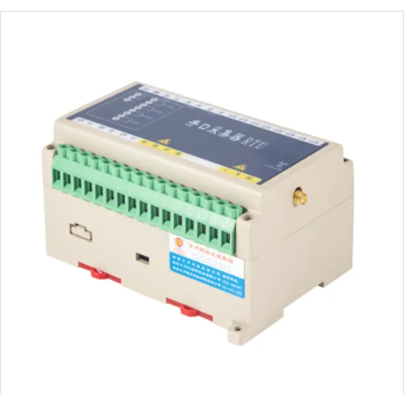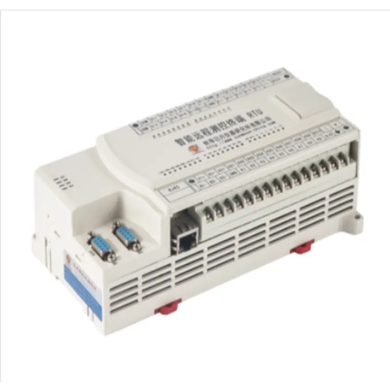
RTU terminal / RTU intelligent remote measurement and control terminal SM40P-5800
Product Categories RTU Terminal
RTU is the main controller for SCADA system to implement measurement and control of oil wells, water wells and booster pump stations. It is an intelligent remote terminal that realizes real-time collection, storage, alarm and control of production process data of the above three measurement and control objects, and meets the application requirements of production sites such as oil wells, water wells and booster pump stations. The design of digital oilfield standardized RTU is designed according to the application of field environment and complex electrical environment, which can meet the various needs of oilfields and harsh natural and electrical environments. At the same time, the design of RTU meets the realization requirements of digital oilfield intelligent functions. According to the standardized and templated design concept, the standardized RTU can meet the on-site application requirements of oil wells, water wells and booster pump stations through simple parameter configuration.
1. Overview
RTU is the main controller for SCADA system to implement measurement and control of oil wells, water wells and booster pump stations. It is an intelligent remote terminal that realizes real-time collection, storage, alarm and control of production process data of the above three measurement and control objects, and meets the application requirements of production sites such as oil wells, water wells and booster pump stations. The design of digital oilfield standardized RTU is designed according to the application of field environment and complex electrical environment, which can meet the various needs of oilfields and harsh natural and electrical environments. At the same time, the design of RTU meets the realization requirements of digital oilfield intelligent functions. According to the standardized and templated design concept, the standardized RTU can meet the on-site application requirements of oil wells, water wells and booster pump stations through simple parameter configuration.
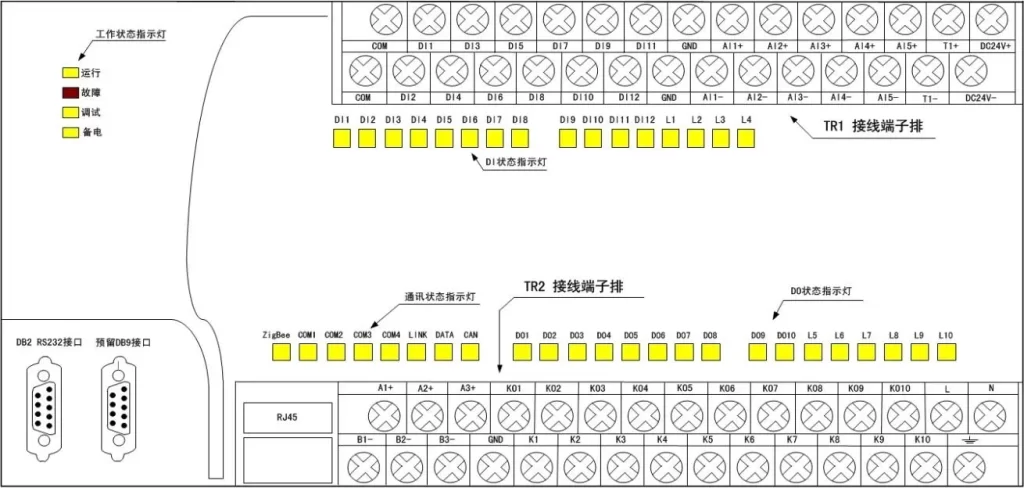
2. Appearance

3. Technical parameters:
| project | illustrate |
| processor | 32-bit microprocessor, main frequency 450MHz |
| Running Memory | 128MB, power-off data preservation |
| FLASH memory | 256MB |
| power supply | AC 180V~265V |
| Backup power supply | DC 24V |
| 6 analog inputs (AI) | 16bits sampling accuracy; input 4~20mA, with overvoltage and overcurrent protection; one channel can be reused as a Pt100 temperature sensor interface |
| 12 digital inputs (DI) | Passive dry node, internal power supply 24V |
| 10 digital outputs (DO) | Relay output, capacity 5A/250VAC, 5A/30VDC |
| 3-way RS485 | Modbus RTU Master Protocol |
| 1-way RS232 | Modbus RTU slave protocol |
| 1 Ethernet RJ45 | Modbus TCP or IEC60870-5-104 protocol |
| 1-way 2.4G ZigBee communication interface | ZigBee PRO 2007 standard, or built-in WIFI function, can be debugged through APP (this function is optional, please specify when ordering) |
| Watchdog, real-time calendar clock | Calendar clock power-off time is saved for 3 months |
| Operating temperature | -40℃~+70℃ |
| Storage temperature | -55℃~+85℃ |
| Relative humidity | 5%~95% no condensation |
| weight | 0.48Kg |


